


How to Replace HTC M9 LCD Screen Assembly
BY Davi | 五月 18th, 2015 | 0 | 2
Tools Needed:
- T5 Torx Screwdriver
- PH00 Phillips Screwdriver
- Case Opening Tool
- Spudger
- Tweezers
- SIM Eject Pin
- Heat Gun or Hair Drier
Step 1: Power off the HTC One M9, then take out the SIM and SD card trays with an eject pin or tweezers.


Step 2: Pry up the bottom side rail, undo the 2 screws with T5 Torx screwdriver.


Step 3: Pry up to separate the LCD assembly with a frame from rear housing.

Step 4: Undo the screws marked in the pic, pry up the adhesive shield then pry up the connectors to release the motherboard.


Step 5: Pry up to release the upper logic board.

Step 6: Pry up the battery flex connector then the battery. (Notice: be careful not to damage the battery flex.)

Step 9: Undo the 3 screws, then remove the earphone jack and charging port assembly.


Step 10: Heat up to soften the adhesive and then insert the case opening too to separate the LCD assembly from the front frame.


Step 11: Replace a brand new HTC One M9 LCD Screen Assembly, putting together with the HTC One M9 front housing.

Step 12: Put the battery back on the front housing.

Step 14: Put the upper mainboard on the top of the phone. (Notice: you need to pay attention to make sure the upper mainboard edges are placed into the right bracket. )

Step 15: Reconnect the volume key flex cable ribbon, SIM card reader flex cable to the board.

Step 16: Fasten 4 Torx 5 screws in the board.

Step 17: Put the charging port back on the frame.

Step 18: Fasten 3 screws in the charging port.

Step 19: Put the loudspeaker back on the frame.

Step 20: Layback the mainboard.

Step 21: Fasten 2 screws in the top board, and the screw underneath the loudspeaker flex cable.


Step 21: Reconnect all the connectors on the motherboard.

Step 22: Press down the volume key on the frame and reconnect all the antennas on the motherboard.


Step 23: Fasten 2 screws in the motherboard.

Step 24: Reassemble the battery door with the rest parts.

Step 25: Fasten 2 screws in the bottom.

Step 26: Put the rubber cover back in the bottom.

Step 27: Insert the SD card and SIM card Tray back.


Any questions, just comment below to let us know. We will reply to you ASAP.
|
|

|
|
|
|
|
|---|


 IOS 17.4 official version pushed to block battery vulnerability
 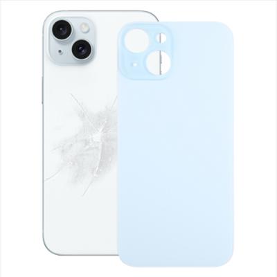 Is the Chinese-made rear case for the iPhone 15 series going on the market?
 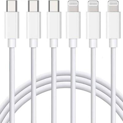 New products coming:USB to MFI Lightning Cable
  Big BUG of iPhone 15
  Successfully submitted!