Loading...
Tools you will need:
-3.jpg) For Case Opening Tool Cell Phone (in-line)
For Case Opening Tool Cell Phone (in-line)
 Case Opening Tool for Cell Phone - Triangle (Thin)


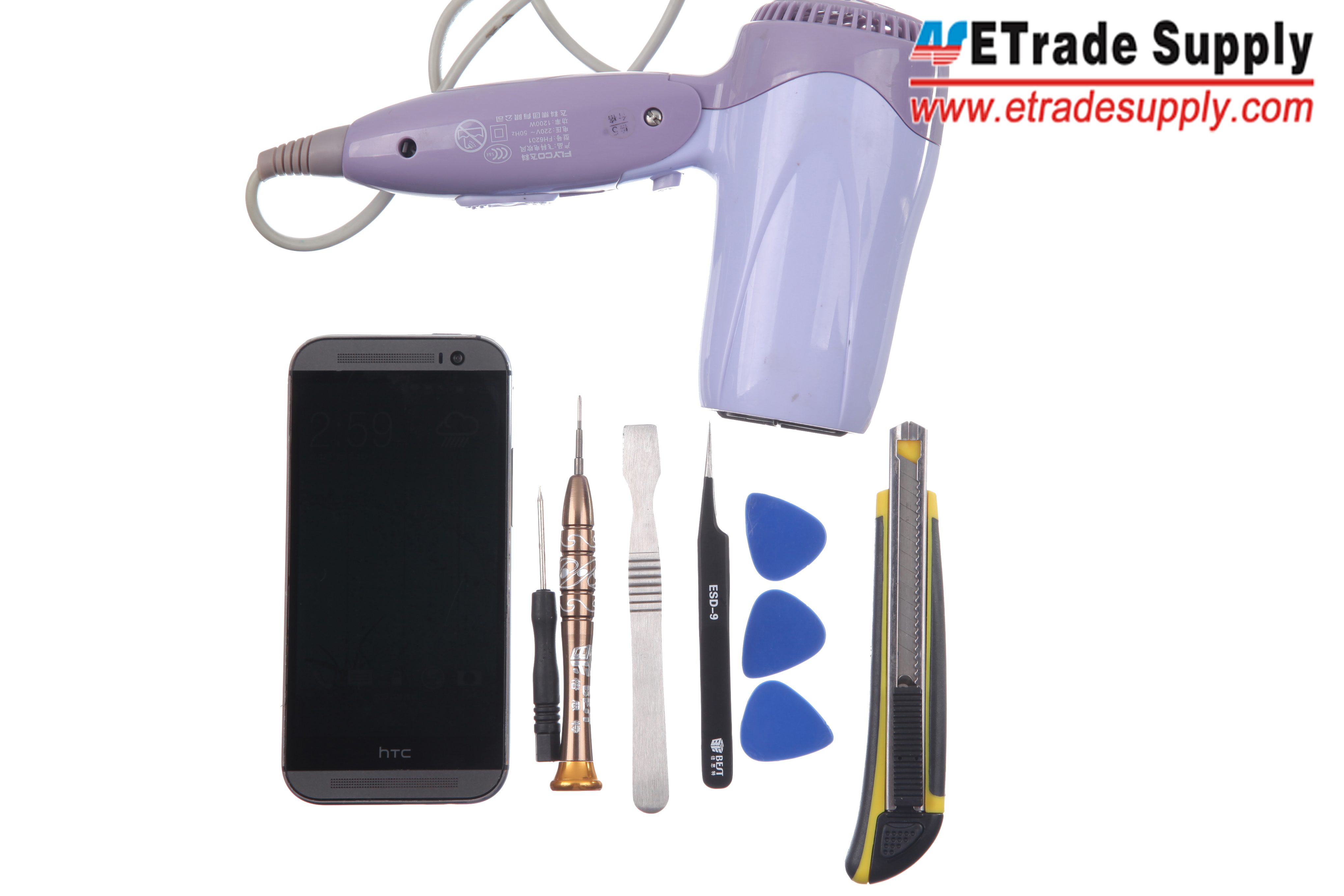
Tools Needed:
Hair Dryer/Heat Gun,
Tweezers,
Cutter Knife,
Metal Spudger Opening Tool,
Plastic Case Opening Tools,
Small Phillips Screwdriver,
T5 Screwdriver.
1. Power off the HTC One M8.

Power off the HTC One M8
2. Heat up the Top and Bottom Cover with a Hair Dryer or a Heat Gun.
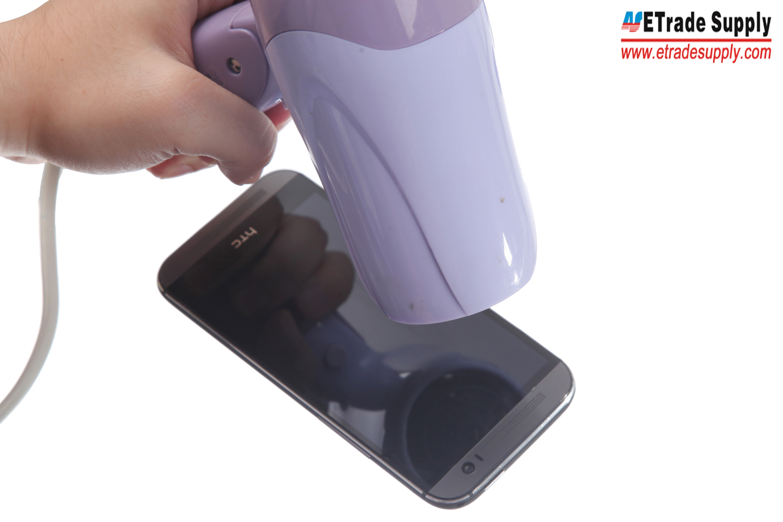
Heat up the Top and Bottom Cover
3. Use a Cutter Knife to pry up the Top and Bottom Cover (please pay special attention during this process).
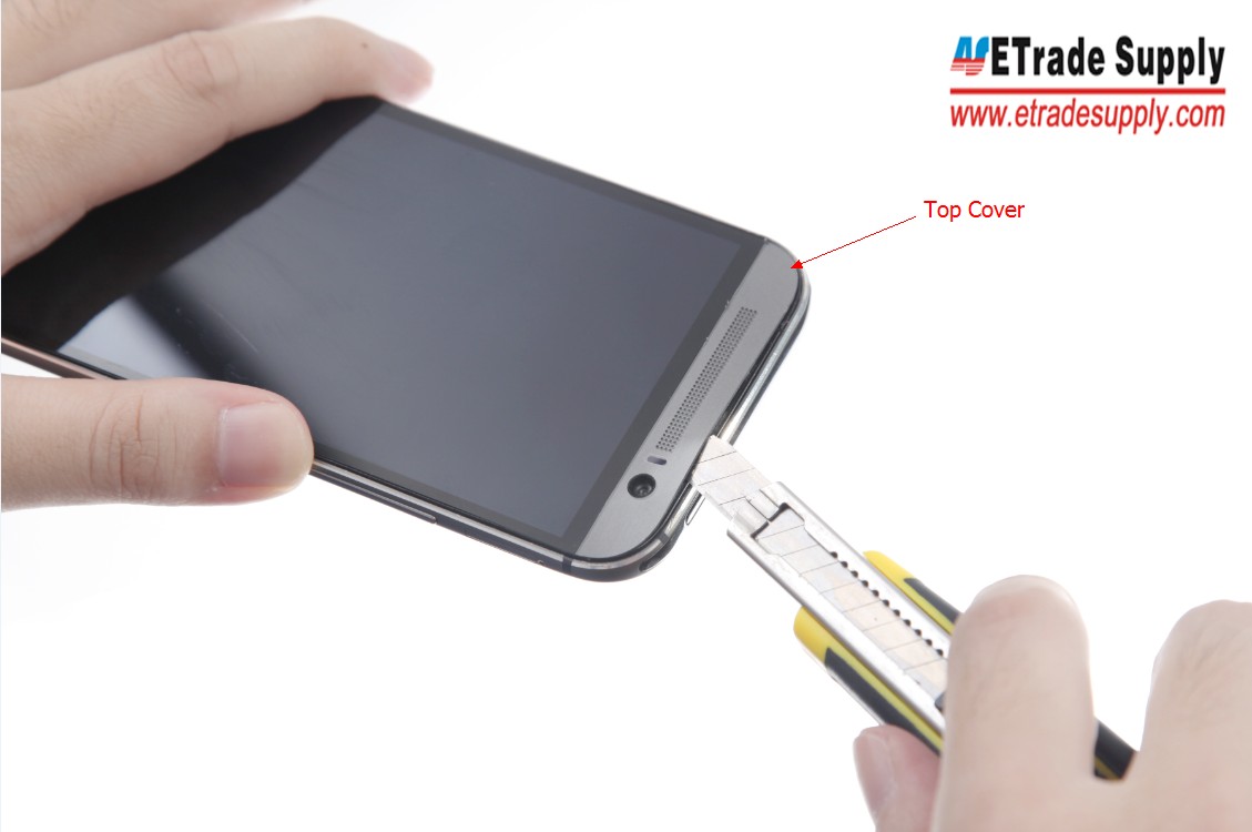
Pry up the Top Cover
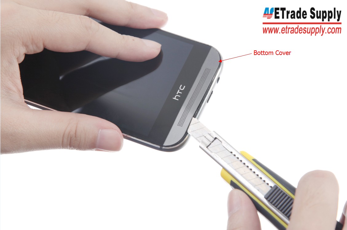
Pry up the Bottom Cover
4. Undo 2 Screws with the help of T5 Screwdriver underneath the Top Cover then 4 Screws with Small Philip Screwdriver underneath the Bottom cover.
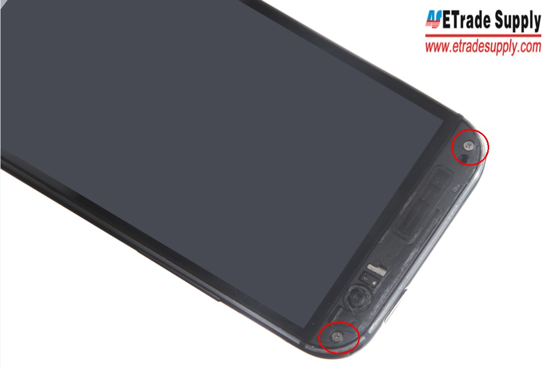
Undo 2 Screws with the help of T5 Screwdriver
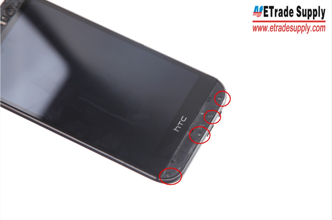
Undo 4 Screws with Small Philip Screwdriver
5. Take out the SIM Card Tray and SD Card Tray with an eject tool or Tweezers.
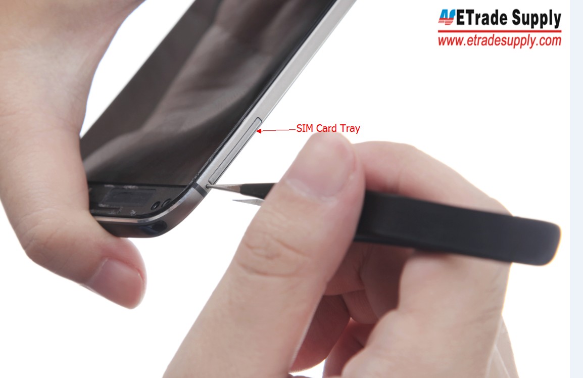
Take out the SIM Card Tray
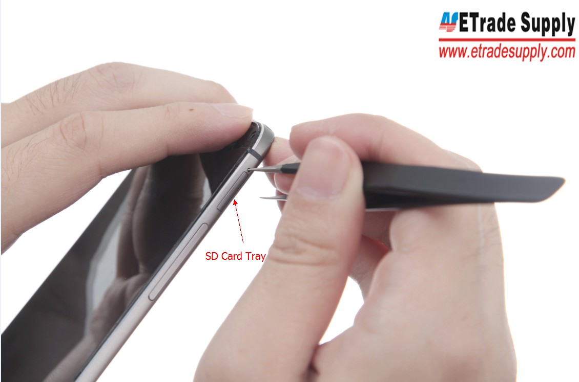
Take out the SD Card Tray
6. Separate the LCD Assembly and Rear Housing with the Cutter Knife.
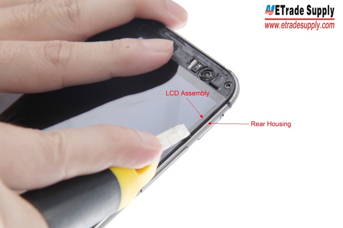
Separate the LCD Assembly and Rear Housing
7. Pry out the LCD Assembly with the Case Opening Tools and Metal Spundger Opening Tool.
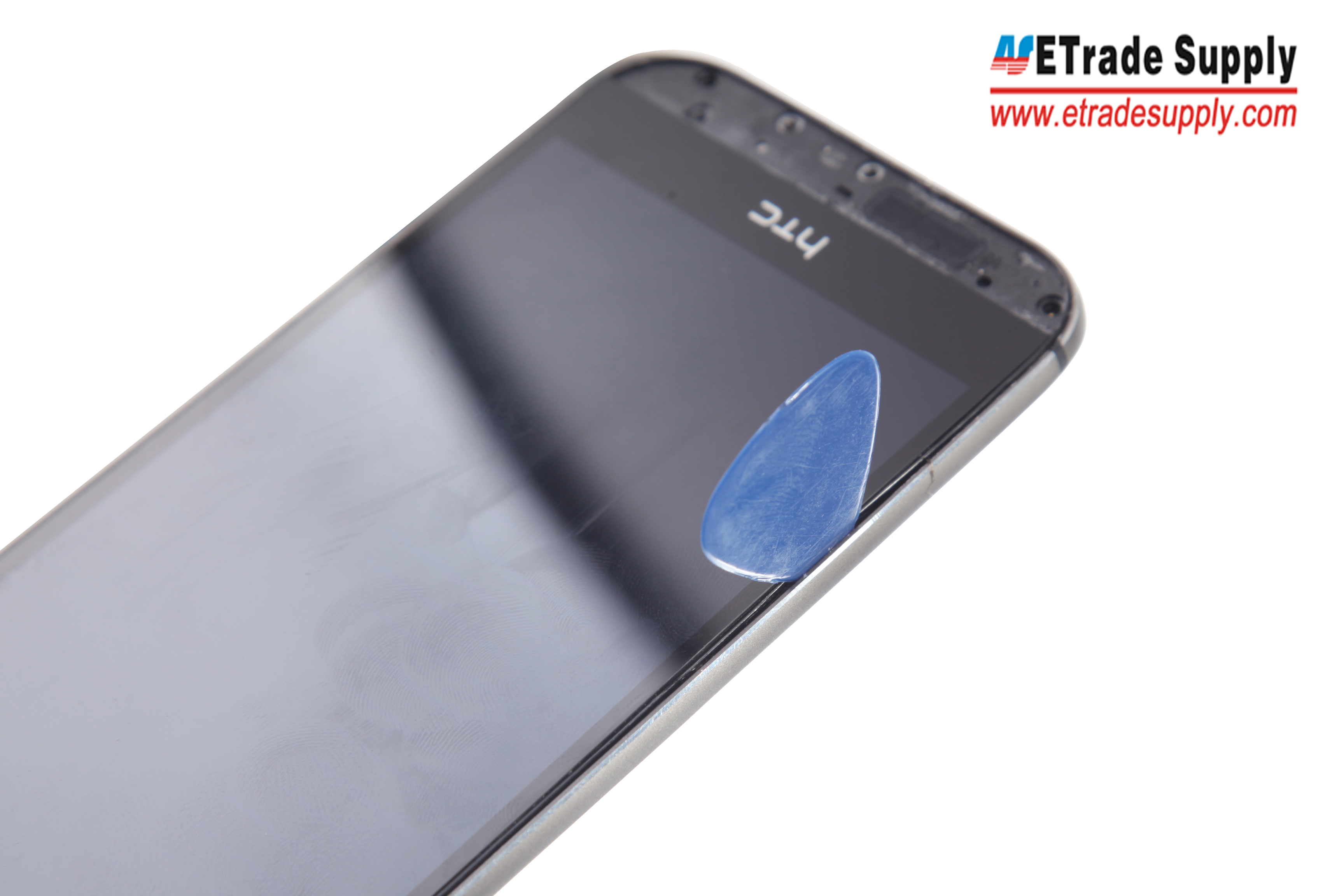
Pry out the LCD Assembly
8. The LCD Assembly and Rear Housing are separated.
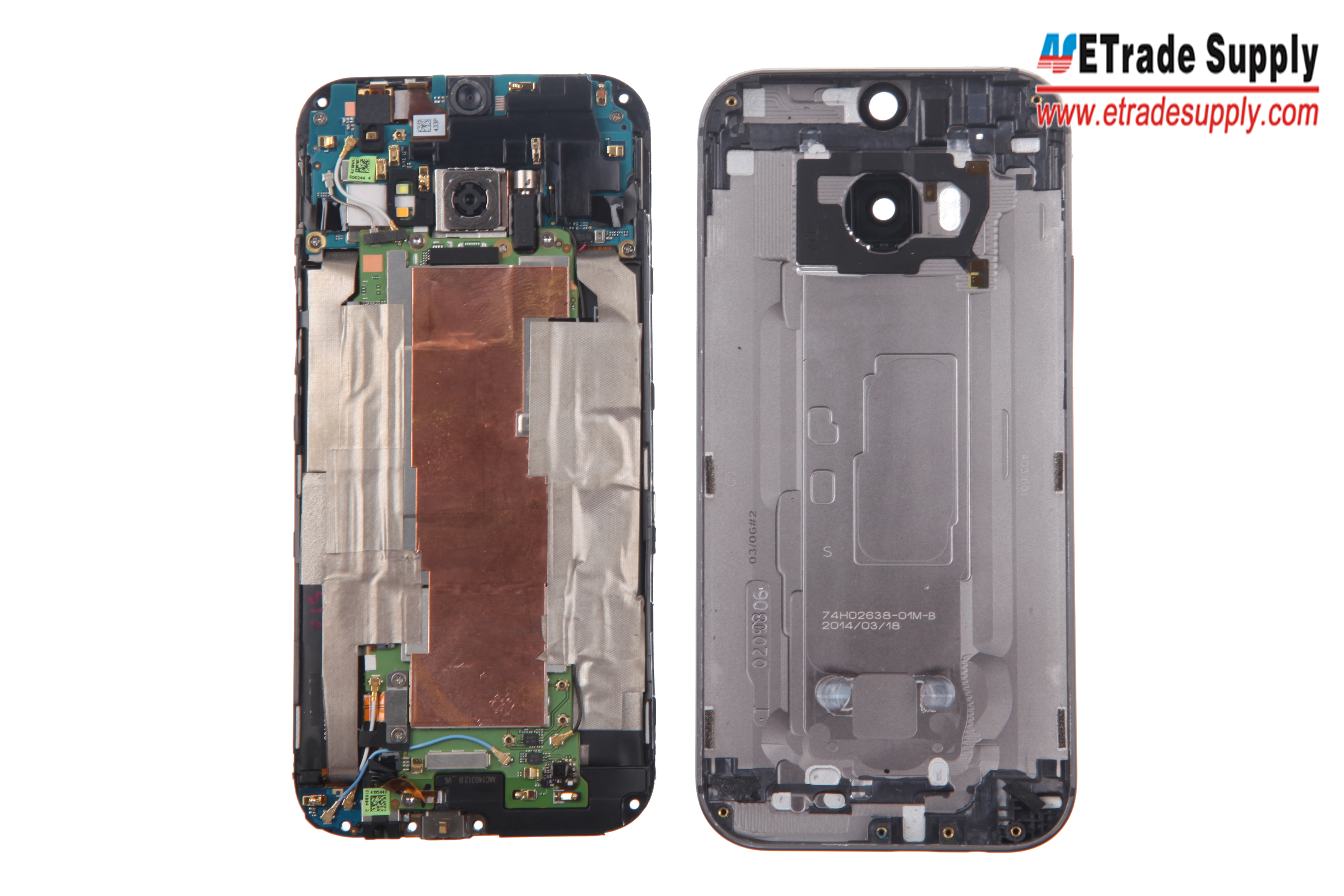
LCD Assembly and Rear Housing
9. Peel off the tapes with the Tweezers.

Peel off one tape
Peel off the other tape
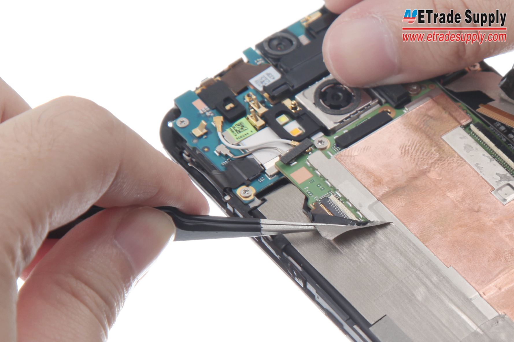
10. Take out the Black Signal Cable with the Tweezers or the Case Opening Tool.
Take out the Black Signal Cable
11. Pry up the 6 connectors with a Case Opening Tool.

Pry up the 2 connectors
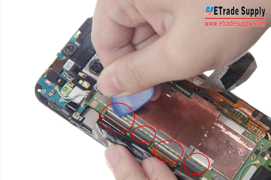
Pry up the other 4 connectors
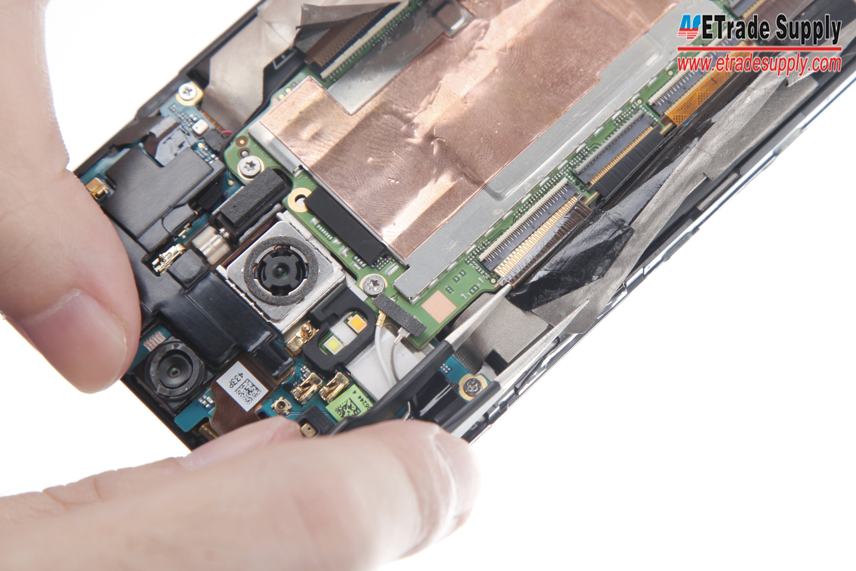
12. Peel off the Charging Port Flex Sticker and pry out the connector with the Tweezers.
Peel off the Sticker and pry out the connector
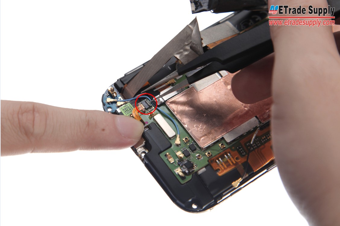
13. Use the Tweezers to pry up the Blue Signal Cable.
Pry up the Blue Signal Cable
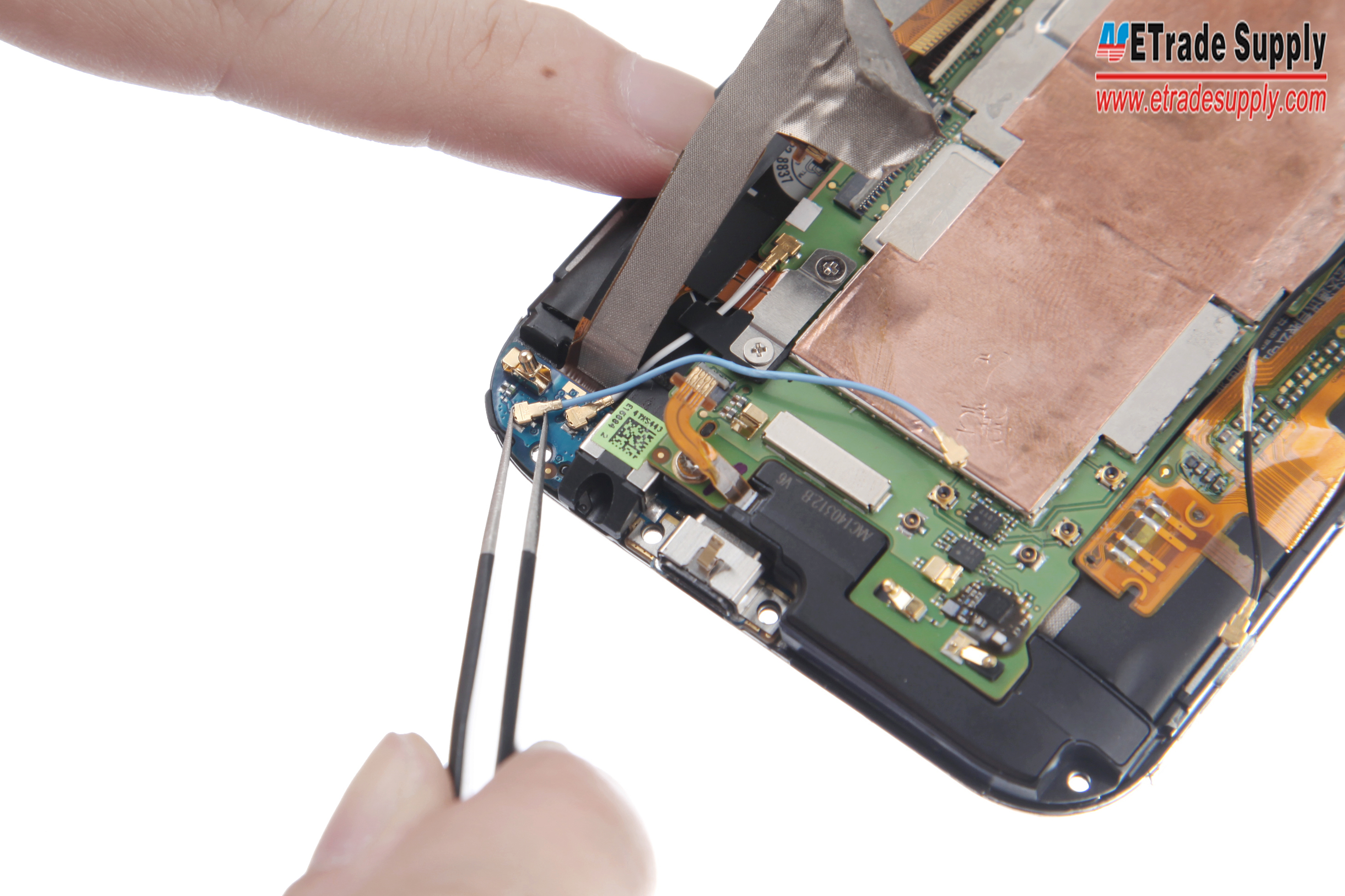
14. Pry up the two White Signal Cables on both upper and bottom parts.
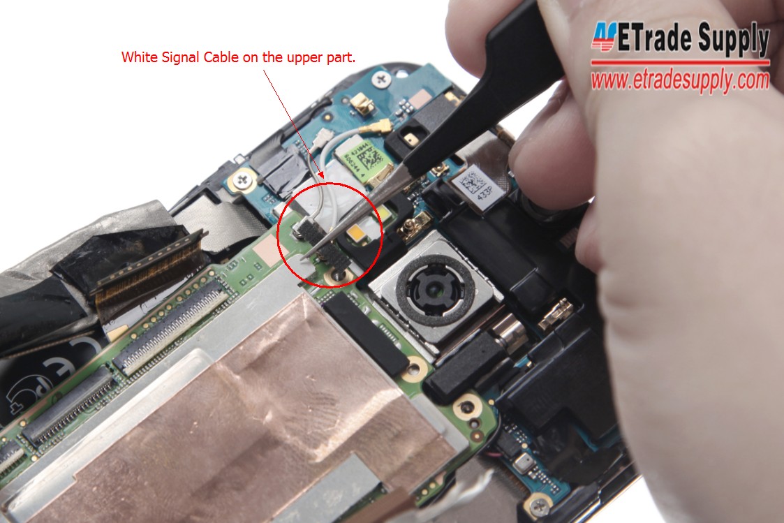
Pry up the White Signal Cable on the upper part
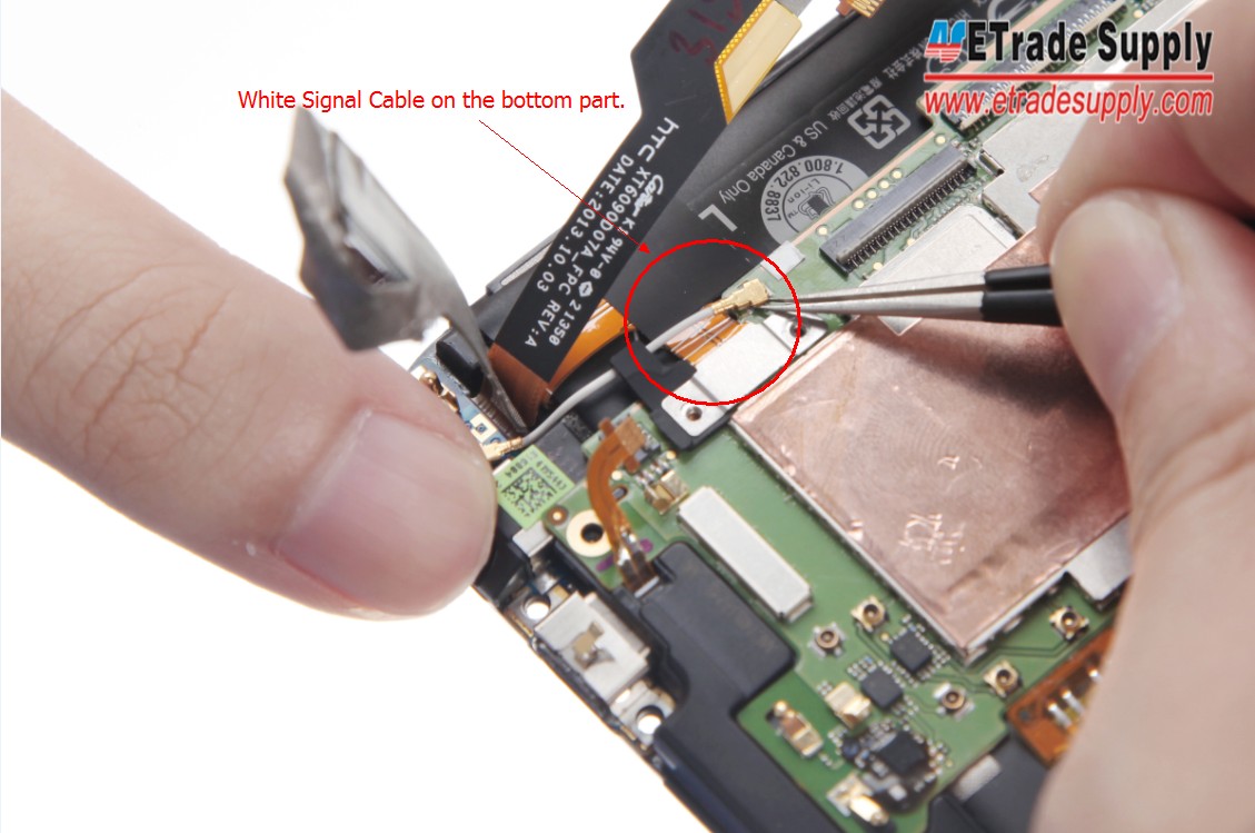
Pry up the White Signal Cable on the bottom part
15. Use the Metal Spudger Opening Tool to pry up the motherboard and then the battery.
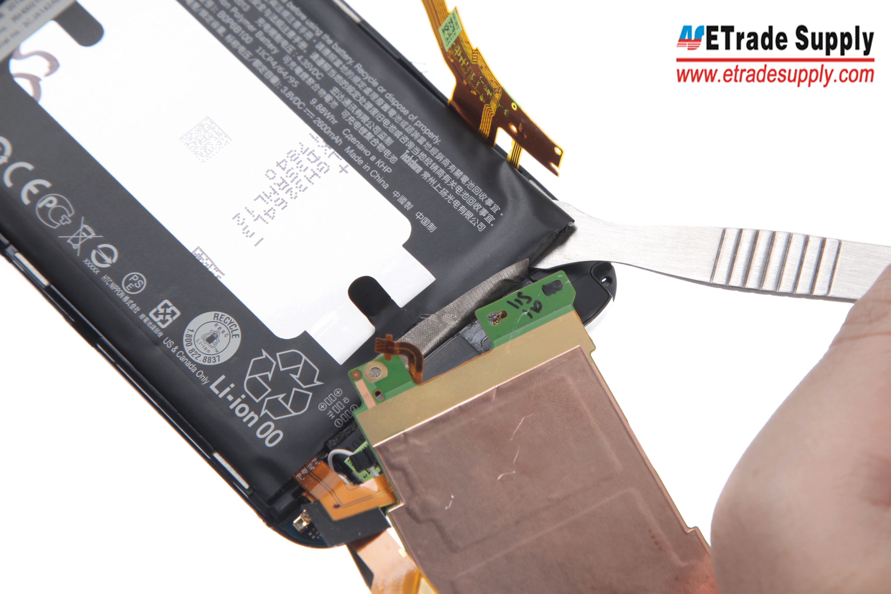
Pry up the motherboard and then the battery
16. Take out the Loud Speaker Assembly and Internal Top Cover.
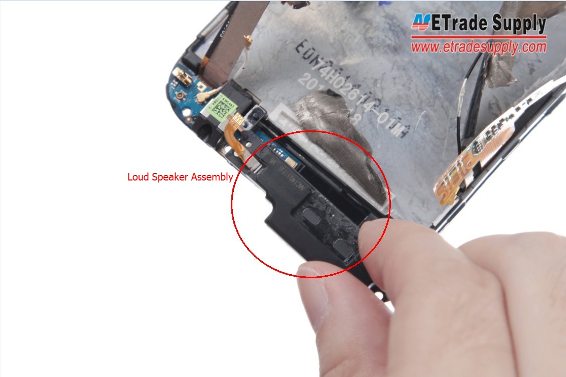
Take out the Loud Speaker Assembly
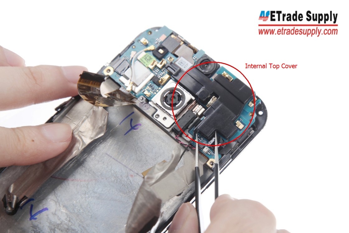
Take out the Internal Top Cover
17. Pry up the 3 Connectors that connect LCD Assembly and Motherboard Flex.
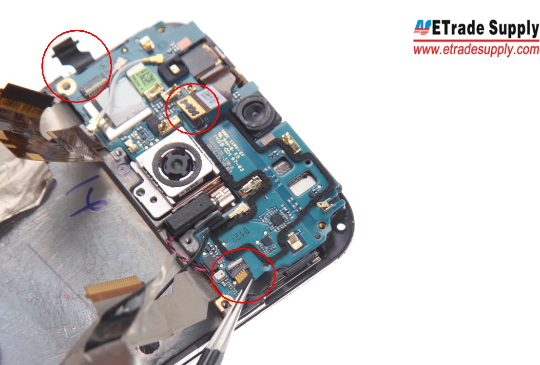
Pry up the 3 Connectors
18. Pry up the Rear Facing Camera and then the Motherboard Flex.
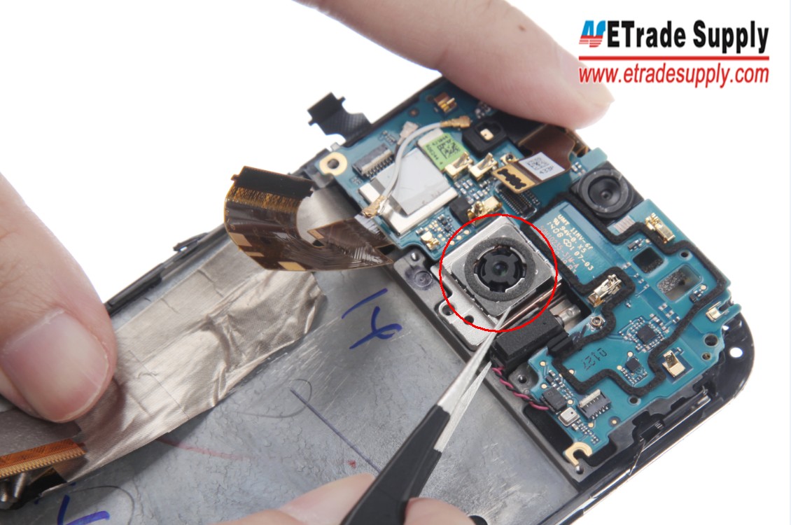
Pry up the Rear Facing Camera
Pry up the Motherboard Flex
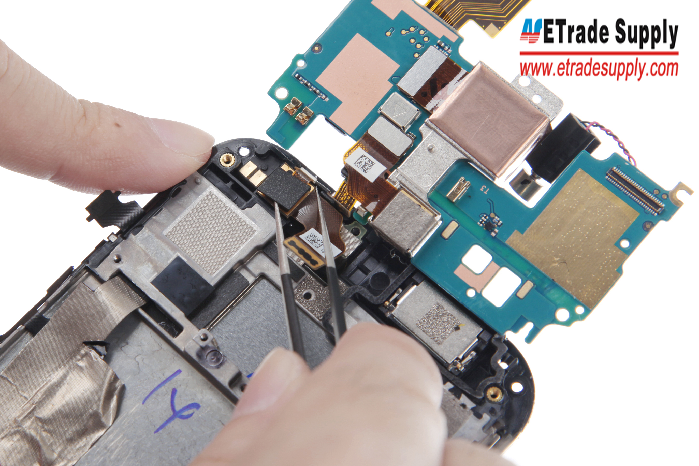
19. Pry up the Rear Facing Camera and Front Facing Camera Connectors.
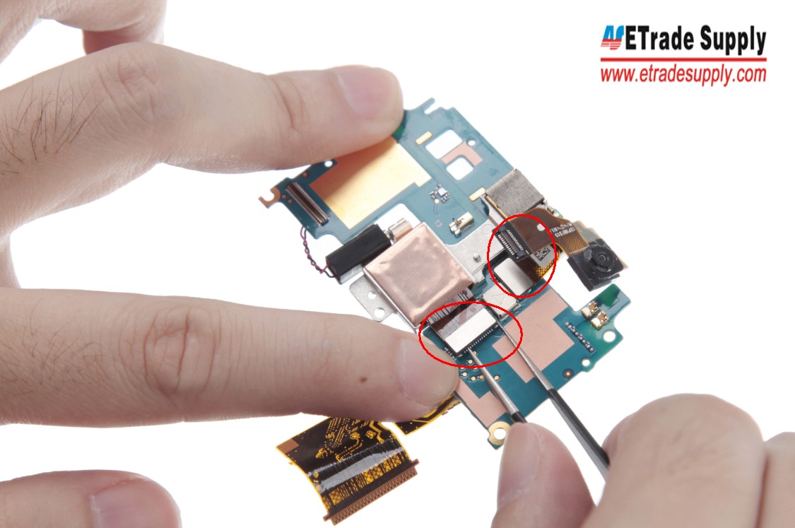
Pry up the Camera Connectors
20. Take out the Ear Speaker.
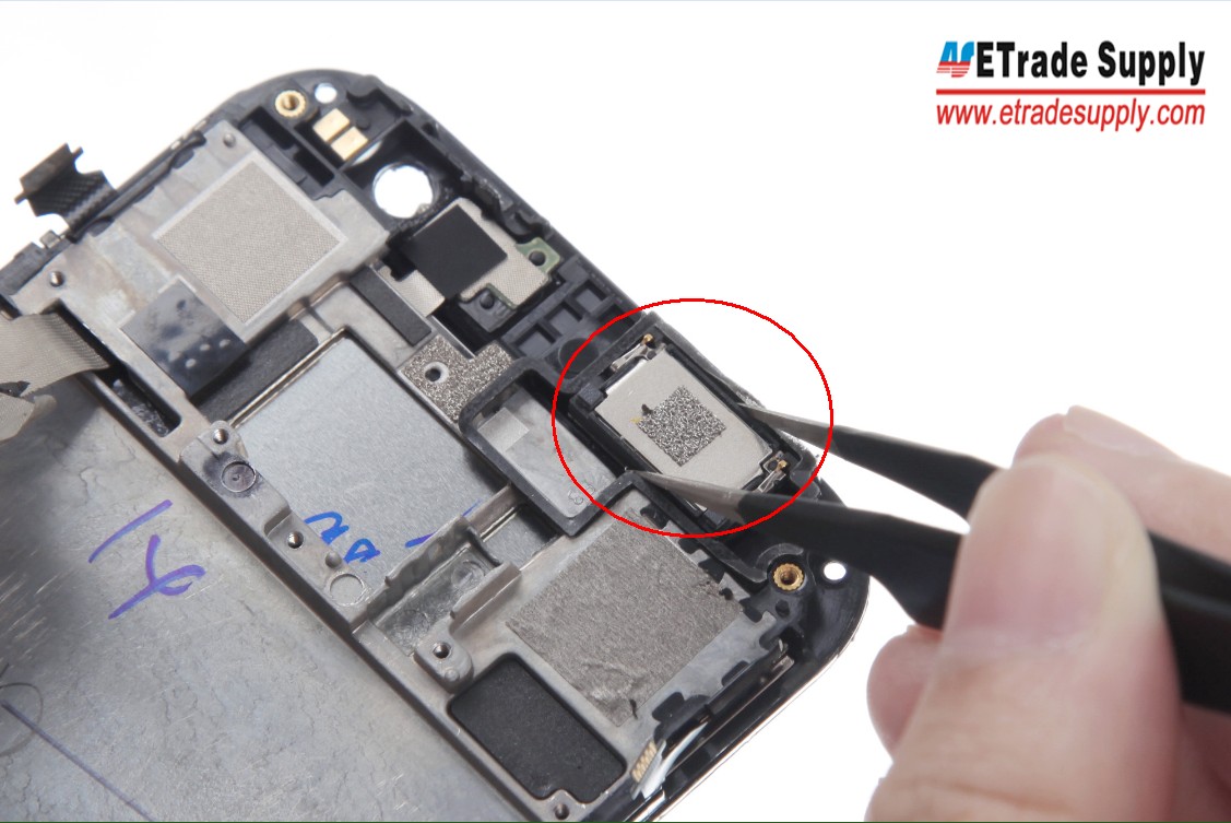
Take out the Ear Speaker
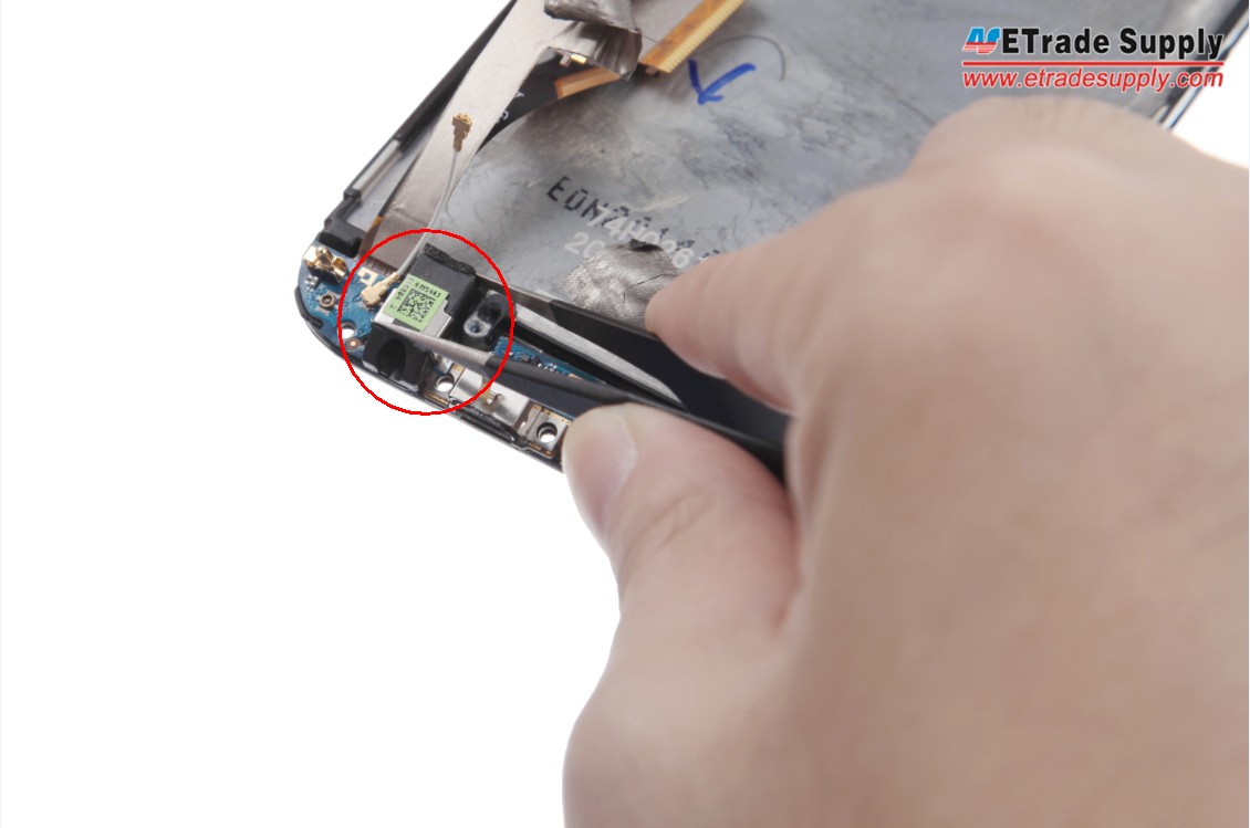
21. Take out the Earphone Jack and the disassembly is finished.
|
|

|
|
|
|
|
|---|


Download and print the repair tutorials here!