


How to Take Apart the Nokia Lumia 1020
BY Junior | 一月 29th, 2014 | 1 | 1
[caption id="attachment_6180" align="alignnone" width="300"][ ]1
]1
How to Repair Cracked Lumia 1020[/caption] This is the Nokia Lumia 1020 take apart repair guide. Following this written repair guide will teach you to disassemble your Lumia 1020 fairly easily in a step by step manner and help you replace the faulty components. We recommend having a dry and dust free work place. It's a great idea to lay the screws and parts out as you pull them to keep them in order and ensure you don't forget or lose anything when assembling your phone.
This guide will help you to change the following Lumia 1020 part(s):
• Lumia 1020 Screen Replacement
• Lumia 1020 Battery Replacement
• Lumia 1020 Rear Housing replacement
• Lumia 1020 Rear Facing Camera
Tutorial: How to Take Apart the Lumia 1020:
The professional smartphone repair tools you need:
T4 Screwdriver.
Case opening tool.
Plastic card.
Tweezers
Detailed Steps on How to ****Take Apart Lumia ****1020 and ****Repair the ****Cracked Screen:
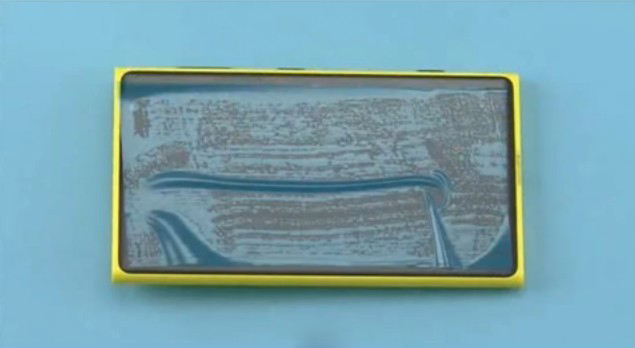
1.The power must be off during the disassembly procedure.
[caption id="attachment_6138" align="alignnone" width="300"][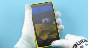 ]2
]2
Power the phone off[/caption]
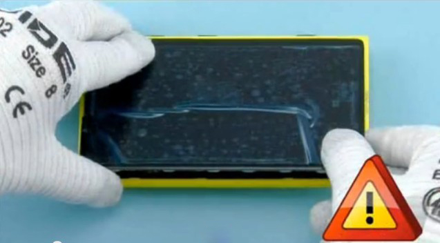
2.Protect the screen with a protective film.
[caption id="attachment_6139" align="alignnone" width="300"][ ]3
]3
Use a protective film to protect the screen[/caption]
3.Remove the SIM tray with the eject tool.
[caption id="attachment_6140" align="alignnone" width="300"][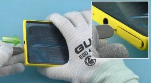 ]4
]4
Remove the SIM tray[/caption]
4.Pull the SIM tray out of the phone.
[caption id="attachment_6141" align="alignnone" width="300"][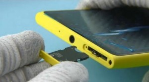 ]5
]5
Take the SIM tray out[/caption]
5.Remove the screw in the order shown.
[caption id="attachment_6142" align="alignnone" width="300"][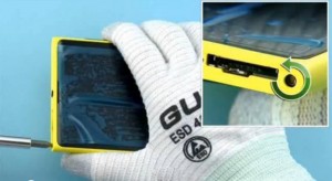 ]6
]6
Remove the screw[/caption]
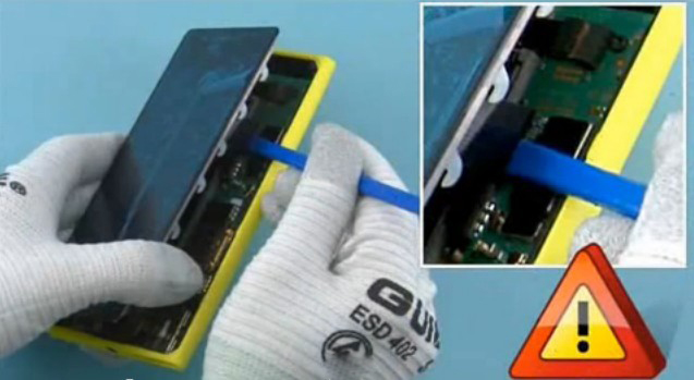
6.Detach the display screen, release the left side as shown. [caption id="attachment_6143" align="alignnone" width="300"][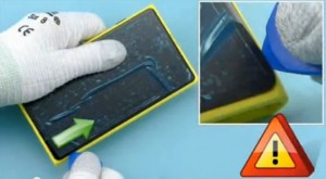 ]7
]7
Detach the display screen[/caption]
7.Lift the left side of the screen up carefully.
[caption id="attachment_6144" align="alignnone" width="300"][ ]8
]8
Lift the left side of the screen up[/caption]
8.Disconnect the battery connector with the plastic opening tool.
[caption id="attachment_6145" align="alignnone" width="300"][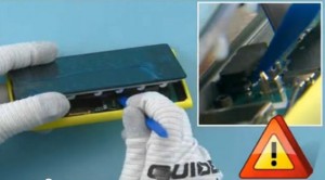 ]9
]9
Disconnect the battery connector[/caption]
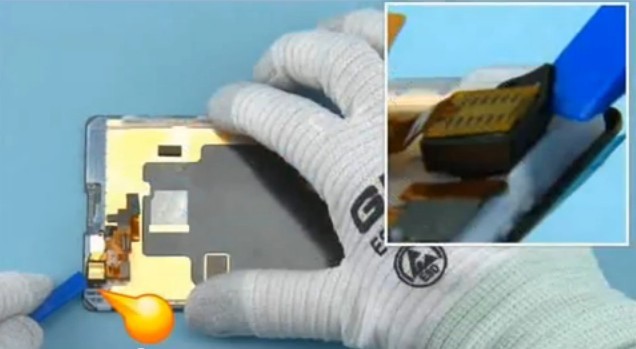
9.Disconnect the camera flex cable connector.
[caption id="attachment_6146" align="alignnone" width="300"][ ]10
]10
Disconnect the camera flex cable connector[/caption]
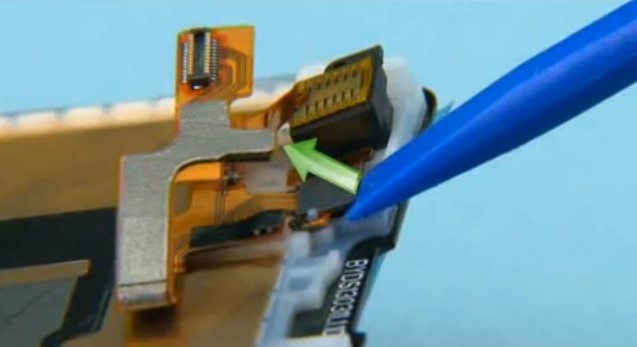
10.Disconnect the screen connector.
[caption id="attachment_6147" align="alignnone" width="300"][ ]11
]11
Disconnect the screen connector[/caption]
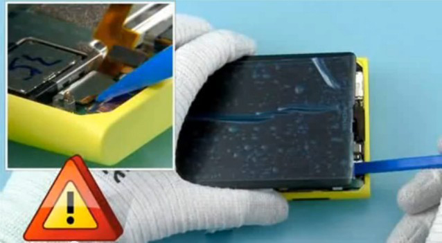
11.Separate the screen assembly from the housing.
[caption id="attachment_6148" align="alignnone" width="300"][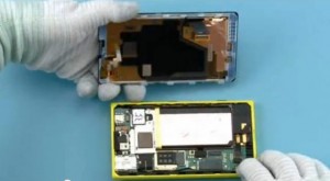 ]12
]12
Separate the screen assembly from the housing[/caption]
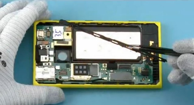
12.Release the camera assembly in the order shown.
[caption id="attachment_6149" align="alignnone" width="300"][ ]13
]13
Release the camera assembly[/caption]
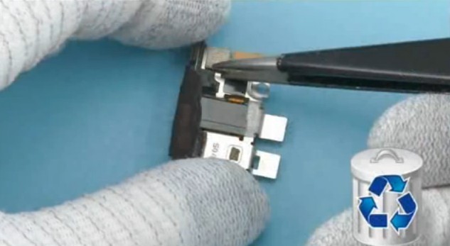
13.Detach the sensor by lifting it as shown.
[caption id="attachment_6150" align="alignnone" width="300"][ ]14
]14
Detach the sensor[/caption]
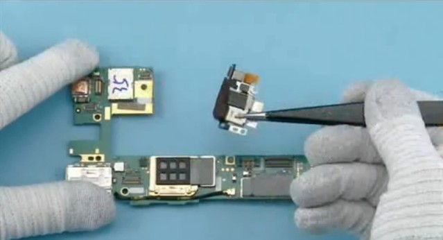
14.Remove the camera assembly.
[caption id="attachment_6151" align="alignnone" width="300"][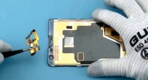 ]15
]15
Remove the camera assembly[/caption]
15.Disconnect the USB connector.
[caption id="attachment_6152" align="alignnone" width="300"][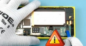 ]16
]16
Disconnect the USB connector[/caption]
16.Remove the screw in the order shown.
[caption id="attachment_6153" align="alignnone" width="300"][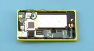 ]17
]17
Remove the screw[/caption]
17.Unscrew the two screws in the order shown.
[caption id="attachment_6154" align="alignnone" width="300"][ ]18
]18
Unscrew the two screws[/caption]
18.Remove the snap which holding the battery holder.
[caption id="attachment_6155" align="alignnone" width="300"][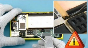 ]19
]19
Remove the snap[/caption]
19.Remove the battery holder.
[caption id="attachment_6156" align="alignnone" width="300"][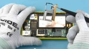 ]20
]20
Remove the battery holder[/caption]
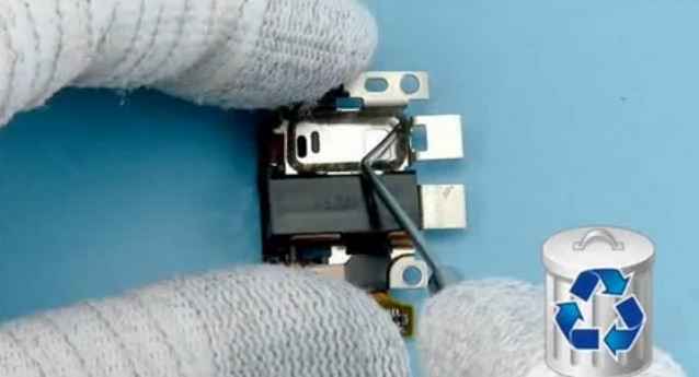
20.Open the camera connector.
[caption id="attachment_6157" align="alignnone" width="300"][ ]21
]21
Open the camera connector[/caption]
21.Lift the camera.
[caption id="attachment_6158" align="alignnone" width="300"][ ]22
]22
Lift the camera[/caption]
22.Detach the locking rail.
[caption id="attachment_6159" align="alignnone" width="300"][ ]23
]23
Detach the locking rail[/caption]
23.Remove the locking rail.
[caption id="attachment_6160" align="alignnone" width="300"][ ]24
]24
Remove the locking rail[/caption]
24.Open the side key flex connector.
[caption id="attachment_6161" align="alignnone" width="300"][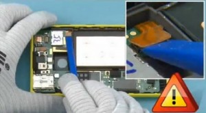 ]25
]25
Open the side key flex connector[/caption]
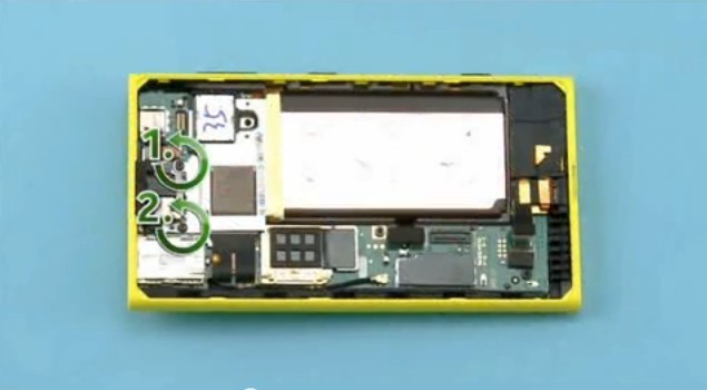
25.Remove the screws in the order shown.
[caption id="attachment_6162" align="alignnone" width="300"][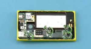 ]26
]26
Remove the screws[/caption]
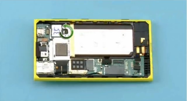
26.Lever the motherboard out carefully and remove it.
[caption id="attachment_6165" align="alignnone" width="300"][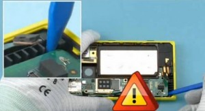 ]28
]28
Lever the motherboard out[/caption]
[caption id="attachment_6166" align="alignnone" width="300"][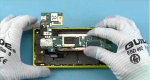 ]29
]29
Remove the motherboard[/caption]
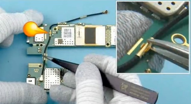
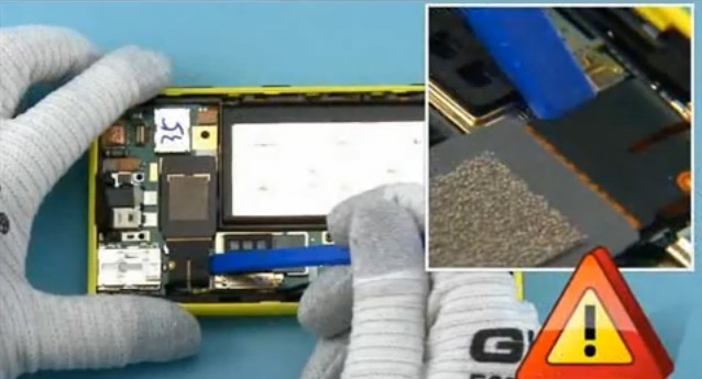
27.Open the AV connector assembly and remove it.
[caption id="attachment_6167" align="alignnone" width="300"][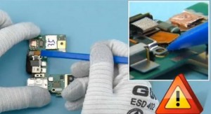 ]30 Open the AV connector assembly[/caption]
[caption id="attachment_6168" align="alignnone" width="300"][ ]31
]31
Remove the AV connector assembly[/caption]
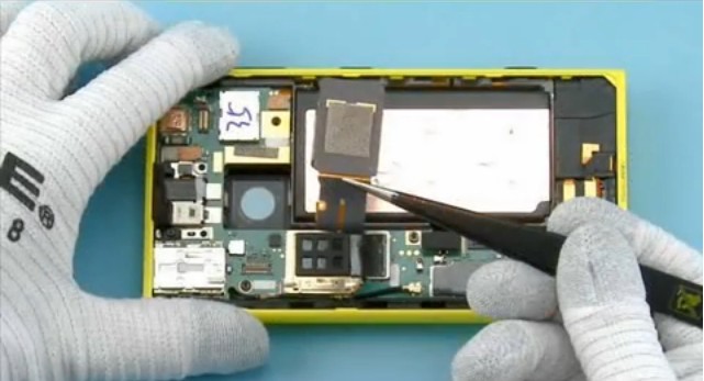
28.Detach the AV frame grounding foam.
[caption id="attachment_6169" align="alignnone" width="300"][ ]32
]32
Detach the AV frame grounding foam[/caption]
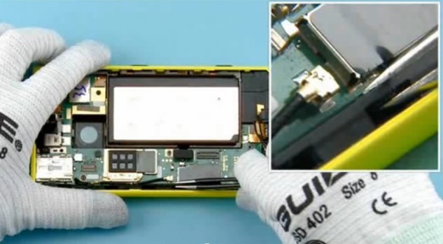
29.Release the earphone and remove it.
[caption id="attachment_6170" align="alignnone" width="300"][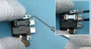 ]33
]33
Release the earphone[/caption]
30.Detach the earphone gasket.
[caption id="attachment_6171" align="alignnone" width="300"][ ]34
]34
Detach the earphone gasket[/caption]
31.Release the antenna in the order shown.
[caption id="attachment_6172" align="alignnone" width="300"][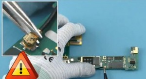 ]35
]35
Release the antenna[/caption]
32.Release and remove the battery.
[caption id="attachment_6174" align="alignnone" width="300"][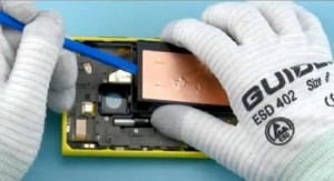 ]37
]37
Remove the battery[/caption]
33.Remove the screws in the order shown.
[caption id="attachment_6175" align="alignnone" width="300"][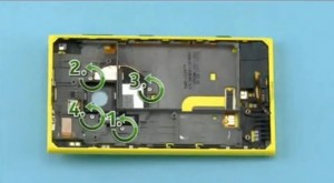 ]38
]38
Remove the screws[/caption]
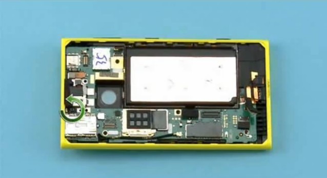
34.Lift up the rear housing assembly to separate the camera xeon flash.
[caption id="attachment_6176" align="alignnone" width="300"][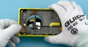 ]39
]39
Lift up the rear housing assembly[/caption]
[caption id="attachment_6177" align="alignnone" width="300"][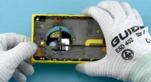 ]40
]40
Separate the camera xeon flash[/caption]
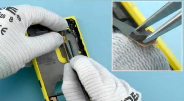
35.Detach the USB gasket.
[caption id="attachment_6179" align="alignnone" width="300"][ ]41
]41
Detach the USB gasket[/caption]
Notice: Welcome to visit our official Twitter, Facebook and YouTube. We will post more DIY repair guide videos and the latest news of upcoming cellphone on these social media platforms.


 IOS 17.4 official version pushed to block battery vulnerability
  Is the Chinese-made rear case for the iPhone 15 series going on the market?
  New products coming:USB to MFI Lightning Cable
  Big BUG of iPhone 15
  Successfully submitted!
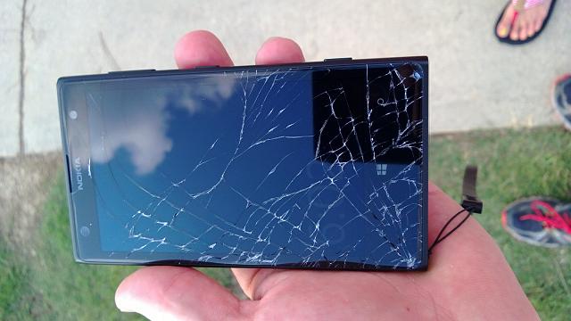
Helped me a lot. I just loosed my screen in a minute. Thanks.